I wanted to change the behaviour of a Fatboy Edison the Petit light so it would be better suited to use as a night light for my son of 6. Currently the lamp only has 3 settings that it cycles through every time you pull the tab.
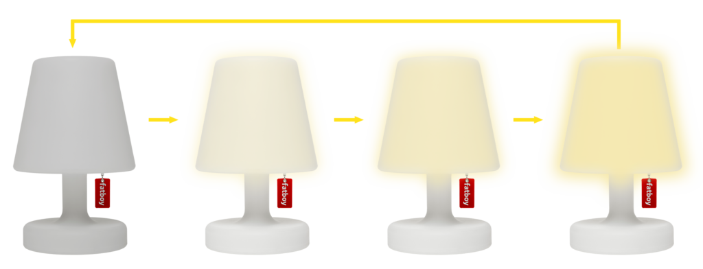
This means that when my son wants to get up during the night to use the bathroom, he always has to go to the full brightness before being able to turn of the light. This bothered me enough to dig in and try to change the control of the lamp.
My idea was to use short and long pulls on the label: short pulls would turn on and off the lamp, long pulls would alternate between dimming up or down for as long as you hold the label down. Somewhere halfway through the project I found this is also how the more recent versions of this lamp work, so I could’ve gone and replaced the PCB with an original, new part, but where’s the fun in that?!
I started by opening the lamp and checking out the PCB. I was already familiar with how the lamp was assembled since some years ago I already opened it up to change the loud clicky tactile switch with a silent version. Fatboy also plays nicely and doesn’t glue or snap fit anything, so you can easily look around in there without breaking anything.
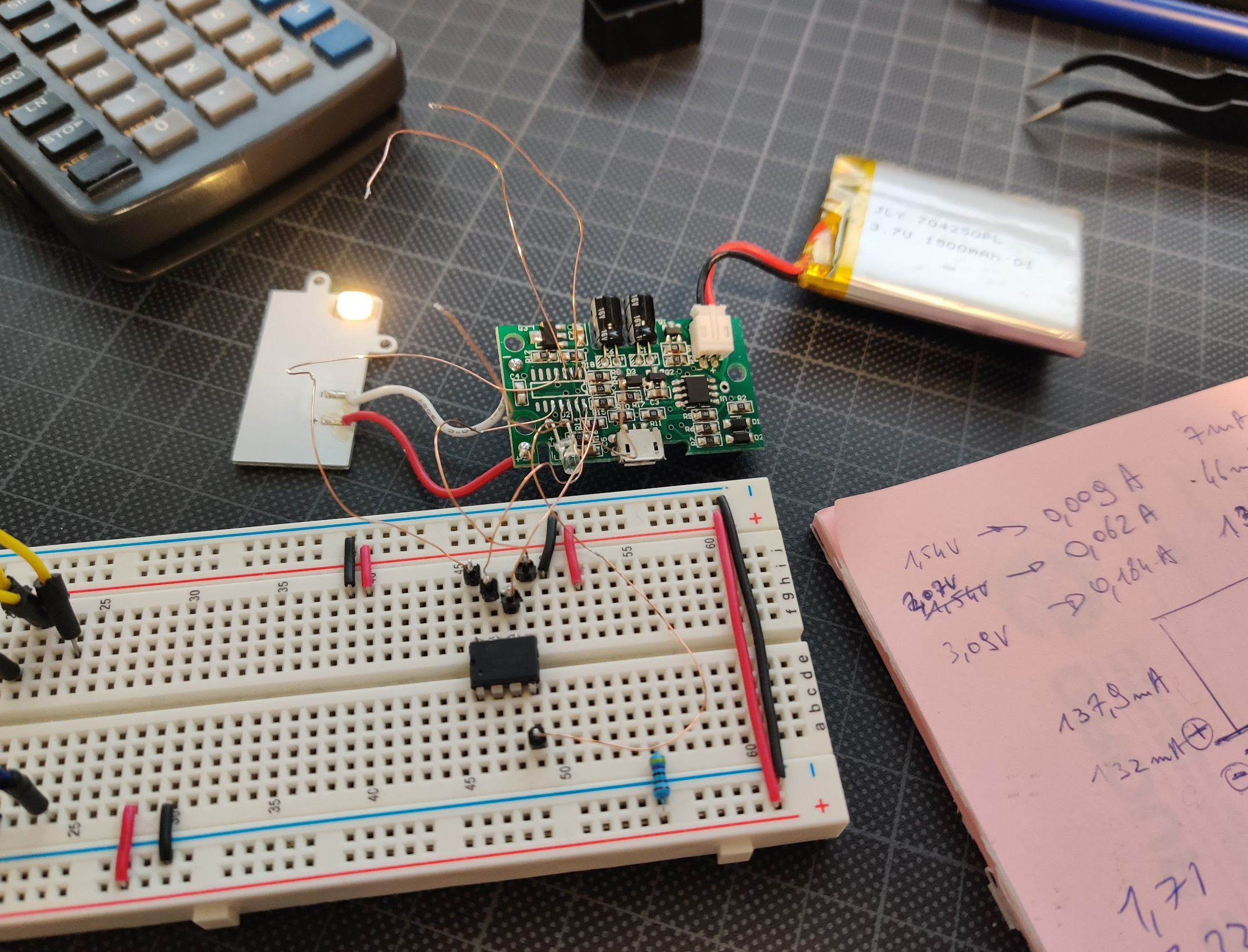
The internals are quite simple: a battery, a small PCB and a single high power LED on an aluminium board for cooling:
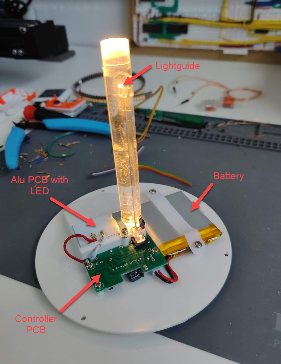
The light is sent up in the shade of the lamp by means of a lightguide with a diffuse tip. Simple but effective.
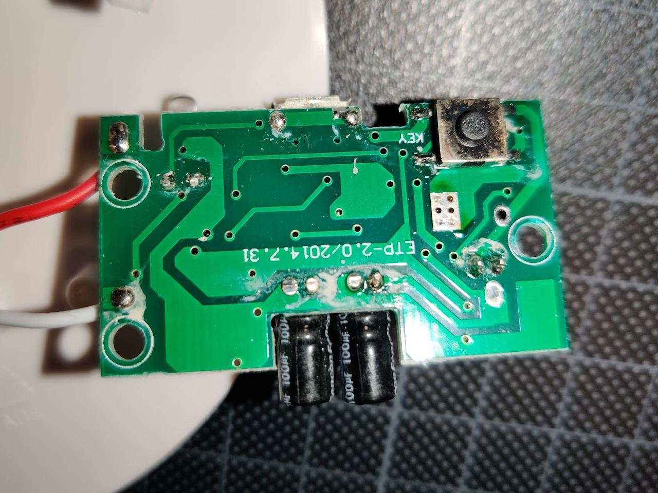
For the PCB I had 2 options: the 2 lamps we have bought a few years apart both had different PCB layouts so I just chose the one that seemed easiest. So it might be that my work is not easily transferrable to a different lamp. Who knows how many variants are out there…
I started by taking pictures of the front and back of the board, flipping one side and overlaying them in Photoshop. Then painting the traces with the help of some backlight revealed the routing of the board. Not all components were labeled: the main microcontroller seems to be of an unknown type with center power pins. I checked several (cheap) µC brands, but couldn’t find any that matched exactly. Probably a very cheap microcontroller with OTP ROM.


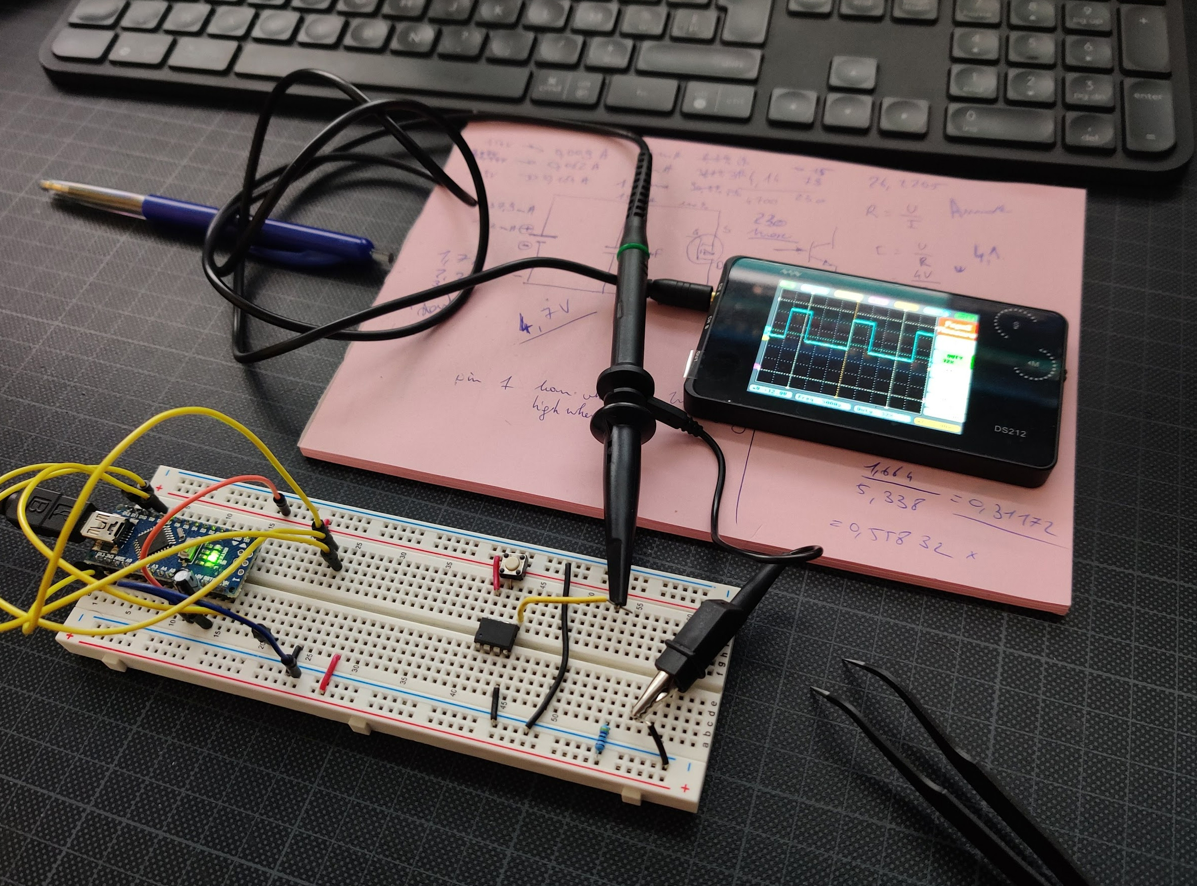
This also showed the interesting locations where to probe the board and check out the signals with a scope. I didn’t have a scope at hand, so I tried this tutorial with a Rpi pico I had laying around.
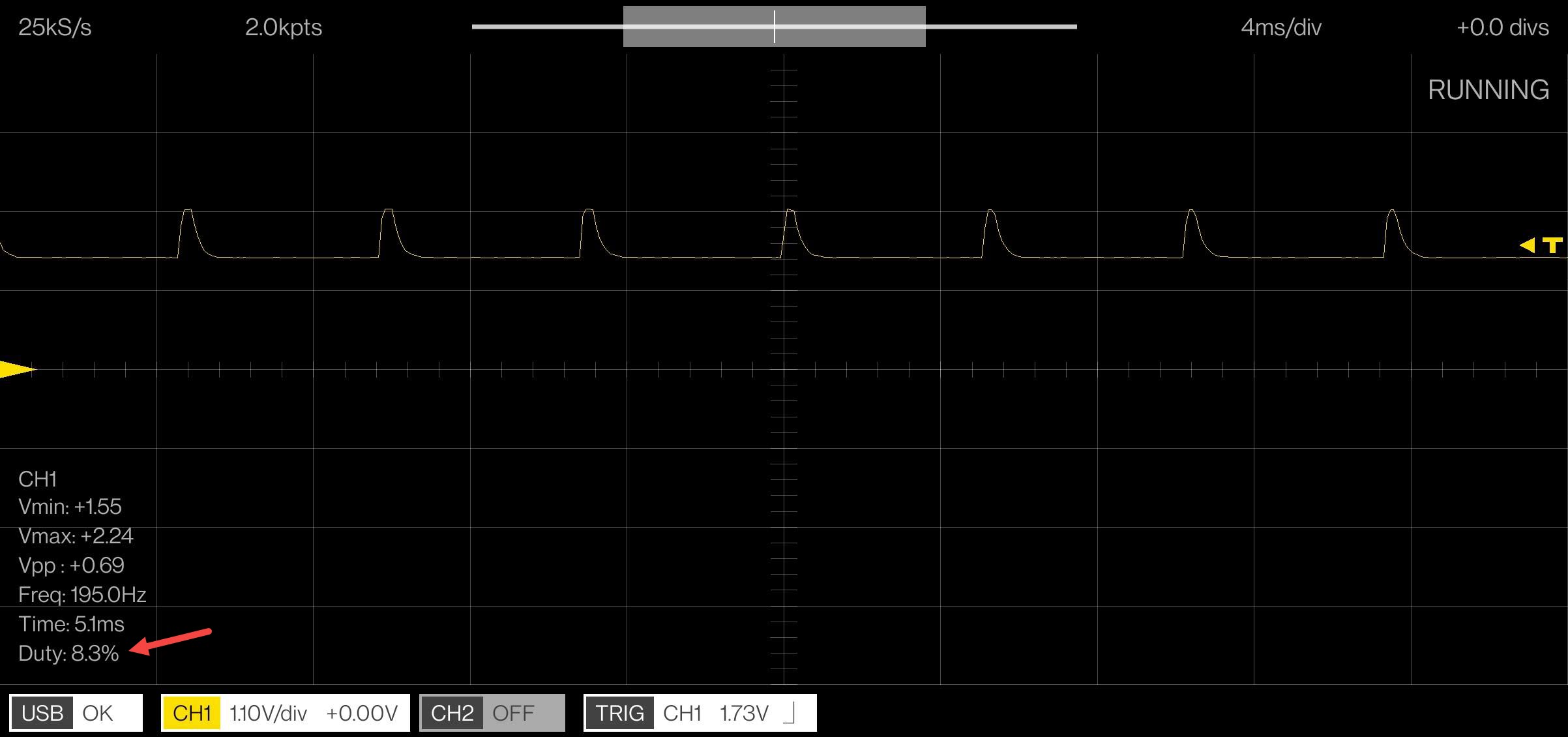


Succes! The LED is driven with a PWM signal (as expected) to create the different brightnesses of the lamp. The Rpi scope was not very detailed nor precise but for what I wanted to see, this was more than enough. It even gave me an idea of the duty cycle in the different settings.
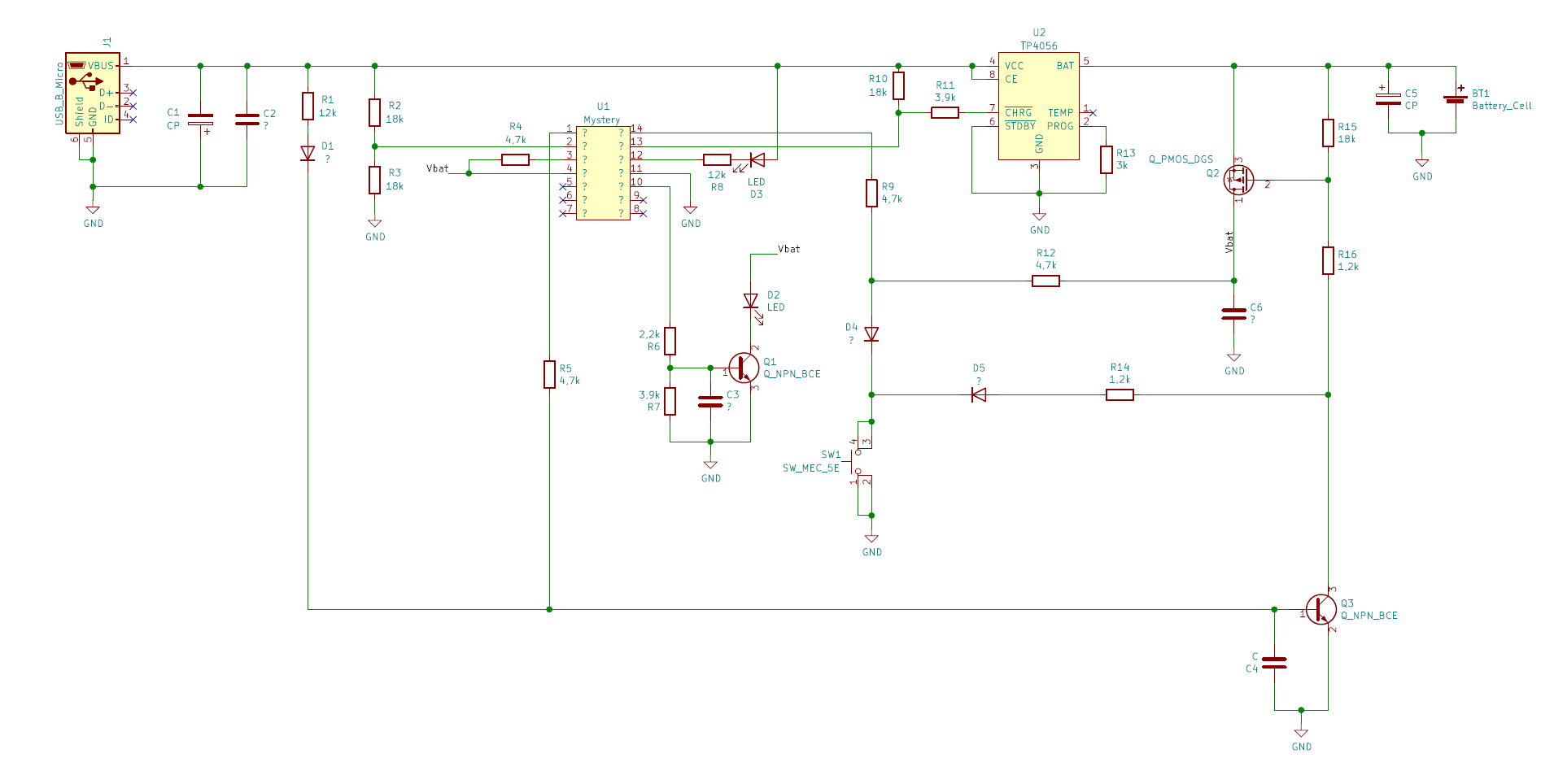
To be able to understand the complete functionality of the board more easily, I transferred the crude Photoshop overlay to a more understandable format in KiCAD.
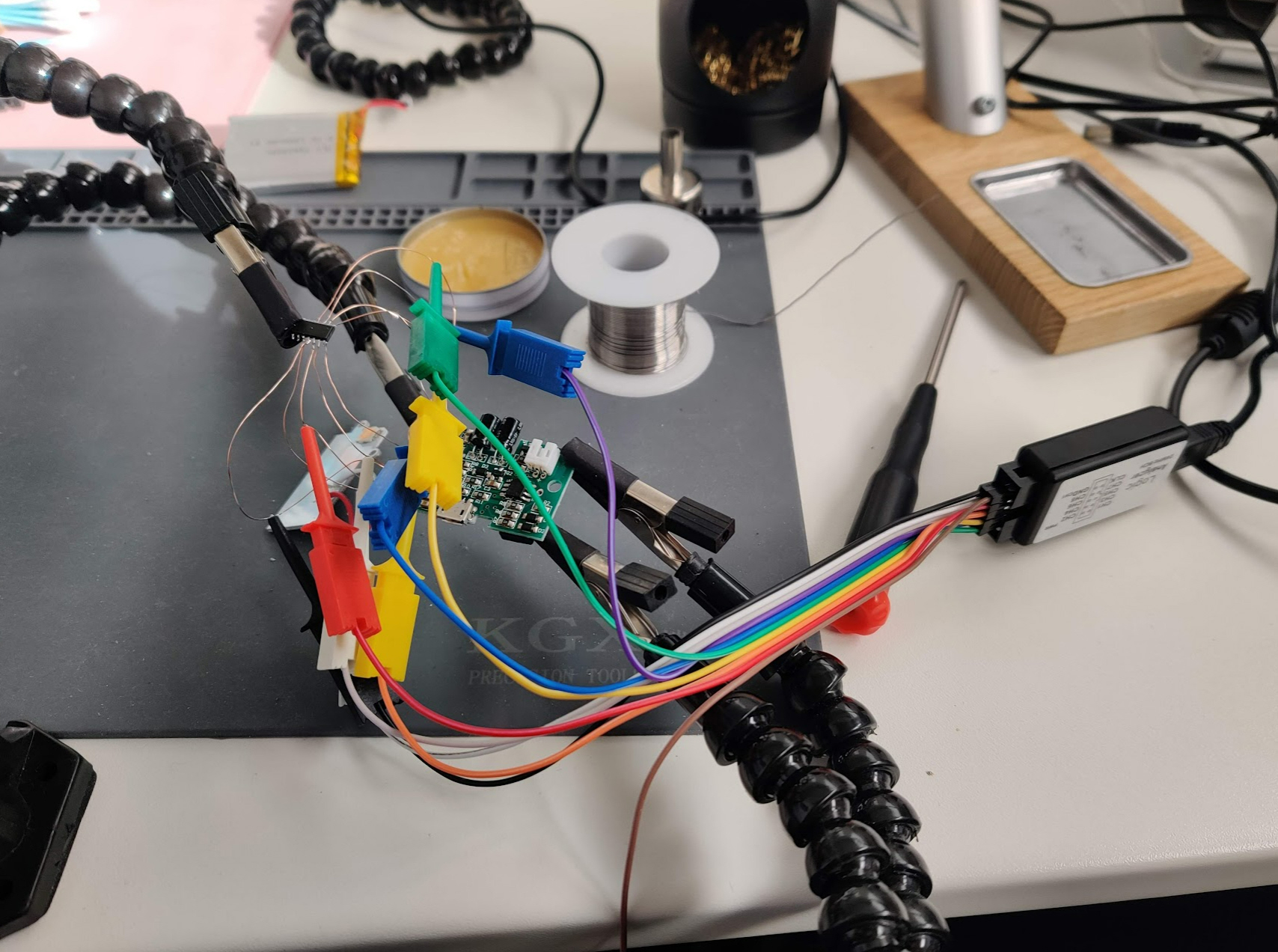
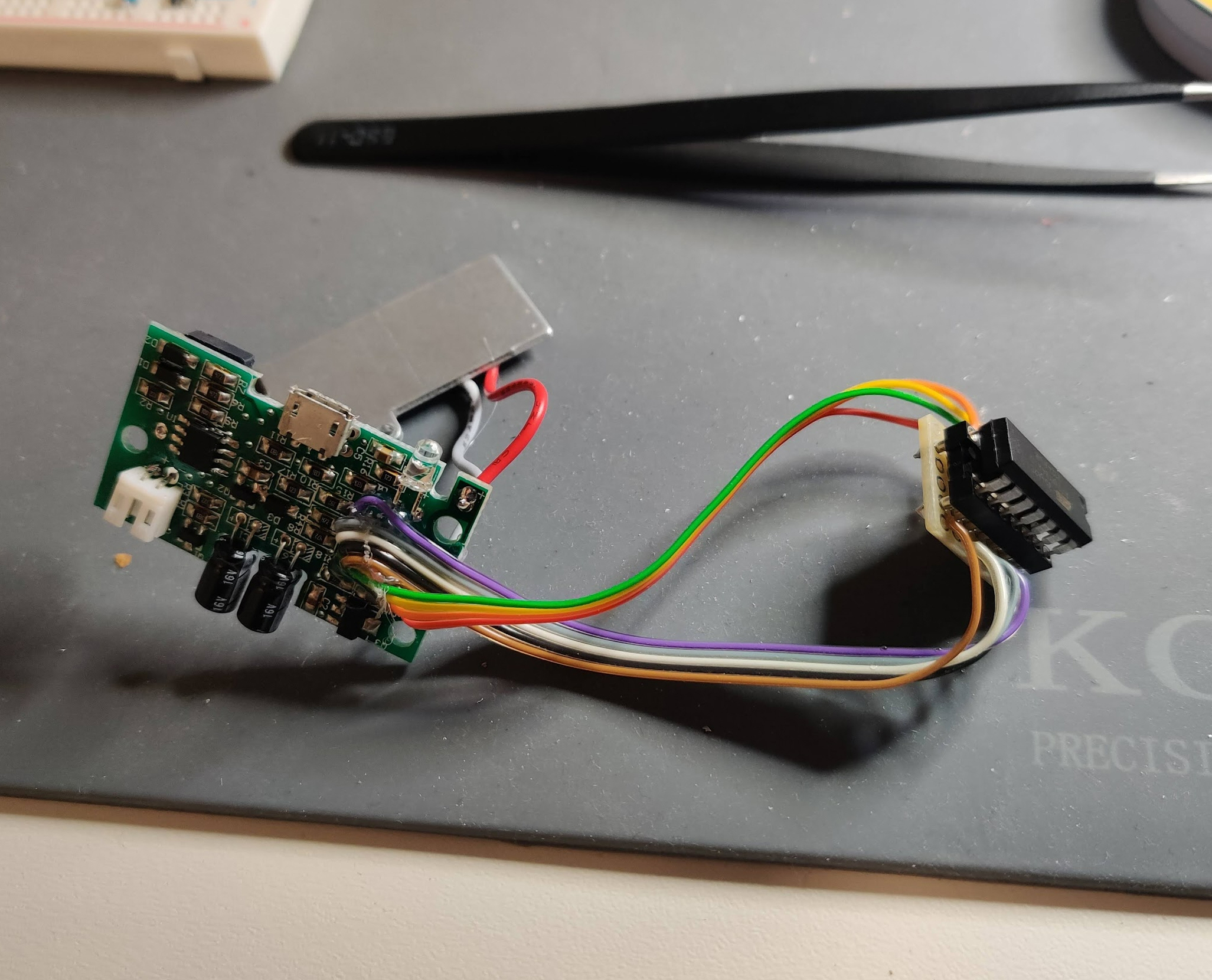
Since it was the plan to replace the unknown microcontroller with an Attiny84, my main concern was to understand the functionality of each pin of the mystery IC. So I ordered a cheap logic analyser from Amazon, and while I was at it I also bought one of those cheap portable oscilloscopes. More toy than tool, but still handy to have laying around.
I desoldered the microcontroller and added some wire to be able to probe the pins more easily and with the help of Pulseview I was able to quickly determine the functionality of each pin.
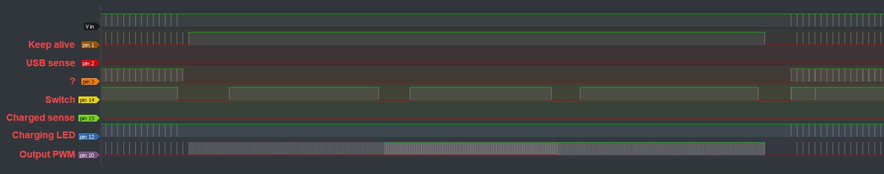
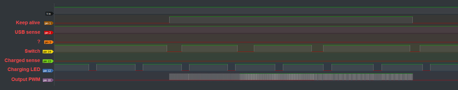
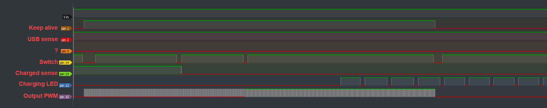
Only pin 3 remained somewhat of a mystery: the microcontroller pulls it low when powered, but there seemed to be no functionality linked with it. I later found that leaving this pin unconnected would have the effect of not being able to turn on the light quickly after it had been turned off.
Having now enough knowledge about the functionality it was easy to select a suitable microcontroller: the Attiny84. I chose that one for several reasons: it’s easily programmable with Arduino IDE (with an Arduino nano as ISP), it works with battery voltage and USB voltage without additional hardware, it has enough GPIO pins and PWM pins and it is more than powerful enough for this application. Since the microcontroller is completely off by the mosfet Q2 when the lamp is off, I shouldn’t consider any low power standby or any other power saving measures. Luckily I was able to find some Attiny84’s in stock but since I already had an Attiny85 at hand I could already start programming and testing.
The code itself really is quite simple and can be found below and on my Github page. The microcontroller starts up after the first button press/label pull and turns on the LED at a low brightness. If the label is held down for longer than a defined value, the brightness starts increasing. When the label is released and pulled again shortly, the lamp turns off by pulling base of Q3 low. If the label is held down again, the lamp now decreases brightness.
There were some special measures taken to have smooth dimming, mainly in the lower regions and I also added a battery voltage measurement. The Attiny can do this completely internally so without any additional hardware. Normally the battery would be drained until the battery protection on the cell itself would kick in, but at 2,9V I found that quite low. Now the lamp will start flashing every 30 seconds when the battery is below 3.15V and it will turn off the lamp at 3.05V, so well within the acceptable range for a LiPo cell.
A final safety I added that was lacking in the original design is prevent the lamp from turning on when the USB is plugged in. I read that it’s not a good idea to use the battery when it is being charged, so now I don’t allow for that use case.
#define PWM_PIN   5       //pin 8 on mystery µC
#define ON_PIN    10      //pin 2 on mystery µC
#define BTN_PIN   1       //pin 12 on mystery µC
#define CHRG_PIN  2       //pin 11 on mystery µC
#define LED_PIN   3       //pin 10 on mystery µC
#define USB_PIN   9       //pin 3 on mystery µC
#define DWN_PIN   8       //pin 5 on mystery µC

#define START_VALUE  25   //brightness level at startup min 60 - max 880
#define B_STEPS      144  //number of brightness steps between min brightness and max brightness

#define LONGPRESS 800     //duration that indicates a long press in ms
#define DIM_DELAY 8       //pause between next dimming step in ms

#define LED_DELAY 200     //pause between blinking of the charging LED in ms

#define V_DELAY 30000     //pause between blinking at low voltage in ms

#define V_TRESHOLD 3050   //min voltage level before the lamp turns off in mV
#define V_BLINK    3150   //min voltage level before the lamp start blinking in mV

const uint16_t PROGMEM brightness[B_STEPS] = {    //brightness look-up table for more linear looking dimming
  60,  61,  62,  64,  65,  66,  67,  69,  70,  72,  73,  74,  76,  77,  79,  81,
  82,  84,  85,  87,  89,  91,  92,  94,  96,  98, 100, 102, 104, 106, 108, 110,
  112, 114, 116, 118, 121, 123, 125, 128, 130, 132, 135, 137, 140, 143, 145, 148,
  151, 153, 156, 159, 162, 165, 168, 171, 174, 178, 181, 184, 187, 191, 194, 198,
  201, 205, 209, 212, 216, 220, 224, 228, 232, 236, 240, 245, 249, 253, 258, 262,
  267, 272, 276, 281, 286, 291, 296, 301, 306, 312, 317, 322, 328, 334, 339, 345,
  351, 357, 363, 369, 375, 382, 388, 395, 401, 408, 415, 422, 429, 436, 443, 451,
  458, 466, 474, 481, 489, 497, 505, 514, 522, 531, 539, 548, 557, 566, 575, 585,
  594, 604, 613, 623, 633, 643, 654, 664, 675, 697, 719, 742, 765, 790, 827, 880
};

boolean prev_btn = false;
boolean btn = false;
boolean bootup = true;
boolean usb = false;
boolean charged = false;

boolean LED_blink = false;

unsigned long start_TS, dim_TS, LED_TS, V_TS;

int b = START_VALUE;
int step_b = 1;

void setup() {
  //set up timer1 for 10-bit resolution, fast PWM,no prescaling
  TCCR1A = _BV(COM1B1) | _BV(WGM10) | _BV(WGM11);
  TCCR1B = _BV(CS10) | _BV(WGM12);

  //defining input/output pins
  pinMode(PWM_PIN, OUTPUT);
  pinMode(ON_PIN, OUTPUT);
  pinMode(BTN_PIN, INPUT_PULLUP);
  pinMode(LED_PIN, OUTPUT);
  pinMode(CHRG_PIN, INPUT);
  pinMode(USB_PIN, INPUT);
  pinMode(DWN_PIN, OUTPUT);

  //check if USB is connected
  usb = digitalRead(USB_PIN);

  //if no usb is connected, turn on the lamp
  if (!usb) {
    analogWrite(PWM_PIN, pgm_read_word(&brightness[START_VALUE]));

    // if the battery voltage is within allowable range, keep the lamp on
    long voltage = readVcc();
    if (voltage > V_TRESHOLD) {
      digitalWrite(ON_PIN, HIGH);
      digitalWrite(LED_PIN, HIGH);
      digitalWrite(DWN_PIN, HIGH);
    }
  }

  start_TS = millis();
}

void loop() {
  //check for button press and USB connection
  btn = !digitalRead(BTN_PIN);
  usb = digitalRead(USB_PIN);


  if (usb) {      //handle charging LED and turn off the lamp when USB is connected
    digitalWrite(PWM_PIN, LOW);
    digitalWrite(DWN_PIN, LOW);

    charged = digitalRead(CHRG_PIN);
    if (charged) {
      digitalWrite(LED_PIN, LOW);
    } else {
      if (millis() - LED_TS > LED_DELAY) {
        LED_TS = millis();
        LED_blink = !LED_blink;
        digitalWrite(LED_PIN, LED_blink);
      }
    }


  } else {   //if no USB is connected...

    //check battery voltage every V_DELAY milliseconds
    if (millis() - V_TS > V_DELAY) {
      long voltage = readVcc();
      if (voltage < V_TRESHOLD) {
        digitalWrite(ON_PIN, LOW);    //turn everything off when battery is too low
      } else if (voltage < V_BLINK) {
        digitalWrite(PWM_PIN, LOW);   //blink the lamp when the voltage is getting critical
        delay(100);
        analogWrite(PWM_PIN, pgm_read_word(&brightness[b]));
      }
      V_TS = millis();
    }

    if (btn && !prev_btn ) {
      start_TS = millis();  //set the timestamp to check for long presses
    }

    if (btn && millis() - start_TS > LONGPRESS) { //if it was a long button press...
      if (millis() - dim_TS > DIM_DELAY) {        //and the dimming delay has expired
        dim_TS = millis();

        b += step_b;                          //increase/decrease brightness

        if (b > B_STEPS - 1) b = B_STEPS - 1; //cap brightness at maximum
        if (b < 0) b = 0;                     //cap brightness at minimum

        analogWrite(PWM_PIN, pgm_read_word(&brightness[b]));
      }
    }

    if (!btn && prev_btn) {
      step_b = -step_b; //reverse brightness dimming direction
      if (bootup) {
        bootup = false; //don't turn off the lamp when it has just been turned on
      } else {
        if (millis() - start_TS < LONGPRESS) { //if it was a short button press, turn of the lamp
          digitalWrite(ON_PIN, LOW);
          digitalWrite(PWM_PIN, LOW);
        }
      }
    }
  }
  prev_btn = btn;
}

long readVcc() {
  // Read 1.1V reference against AVcc
  // set the reference to Vcc and the measurement to the internal 1.1V reference
#if defined(__AVR_ATmega32U4__) || defined(__AVR_ATmega1280__) || defined(__AVR_ATmega2560__)
  ADMUX = _BV(REFS0) | _BV(MUX4) | _BV(MUX3) | _BV(MUX2) | _BV(MUX1);
#elif defined (__AVR_ATtiny24__) || defined(__AVR_ATtiny44__) || defined(__AVR_ATtiny84__)
  ADMUX = _BV(MUX5) | _BV(MUX0);
#elif defined (__AVR_ATtiny25__) || defined(__AVR_ATtiny45__) || defined(__AVR_ATtiny85__)
  ADMUX = _BV(MUX3) | _BV(MUX2);
#else
  ADMUX = _BV(REFS0) | _BV(MUX3) | _BV(MUX2) | _BV(MUX1);
#endif

  delay(2); // Wait for Vref to settle
  ADCSRA |= _BV(ADSC); // Start conversion
  while (bit_is_set(ADCSRA, ADSC)); // measuring

  uint8_t low  = ADCL; // must read ADCL first - it then locks ADCH
  uint8_t high = ADCH; // unlocks both

  long result = (high << 8) | low;

  result = 1125300L / result; // Calculate Vcc (in mV); 1125300 = 1.1*1023*1000
  return result; // Vcc in millivolts
}
The final result:

before….
and after…